
Page 311 - Pafana
P. 311
IV. PŁYTKI WIELOOSTRZOWE INDEXABLE INSERTS МНОГОГРАННЫЕ ПЛАСТИНЫ
turning
technical information
Due to correct chipbreaker process, the feed rate should not be smaller than values showed on chip breaking
diagrams for chosen insert. When the Machine - Clamping - Workpiece - Tool system is not rigid enough and high
achieving quality surface roughness required low values of corner radius r using.
e
During finish machining both parameters f and r should be optimized. Small radius and
e
f ł f are the starting values for assuming right chip breaking.
(max)
Rough machining: IV.
High values of r and f are recommended however, feed rate should not exceed maximal values:
e
- for square S and rhombic C inserts f ł (0,6 - 0,7) r
e
- for triangle T and rhombic D inserts f ł (0,4 - 0,6) r
e
G. Selection of cutting grade.
Selected inserts area are available in different grade, indicated in catalogue. Characteristics of each grade and ISO
application group are shown in Page No. 232-246 and 269-281, of catalogue as well as information concerning
TiN, TiCN, AL O , TiAIN coatings, applied chemically (CVD) or physically PVD).
2
3
Grades of higher wear resistance are recommended for finishing. Grade of high toughness are suitable for roughing.
There is strong relationship between type of chipbreaker and cutting grade in most of PAFANA inserts, what helps
to select the optimal insert. Grades which should be selected as the first choice are indicated in catalogue
by symbol.
H. Selection of machinning parameters.
The selection of right cutting date for specific operation depends on:
- the kind of machining workpiece (its proprieties), - the type of machining ( finishing, medium - finishing, roughing ),
- the typ of machine ( its technical shape ), - and earlier well-chosen tools and inserts (grade and chipbreaker ) .
At the selection of cutting parameters, feed rate f , depth of cut a and cutting speed V one should to use below
0 p
rules:
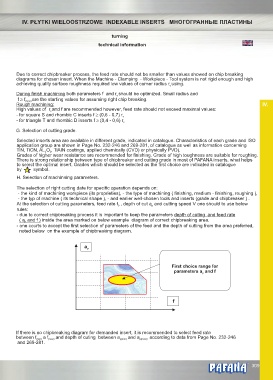
- due to correct chipbreaking process it is important to keep the parameters depth of cuting and feed rate
( a and f ) inside the area marked on below example diagram of correct chipbreaking area.
p
- one courts to accept the first selection of parameters of the feed and the depth of cutting from the area preferred,
noted below on the example of chipbreaking diagram.
a p
First choice range for
parameters a and f
p
f
If there is no chipbreaking diagram for demanded insert, it is recommended to select feed rate
between f (min) a f (max) and depth of cuting between a p(min) and a p(max) , according to data from Page No. 232-246
and 269-281.
®
309