
Page 209 - Pafana
P. 209
III. NARZĘDZIA OBROTOWE ROTARY TOOLS ОБОРОТНЫЕ ИНСТРУМЕНТЫ
3.1. modułowy system wytaczarski “MULTI PAFANA” / boring modular system “MULTI PAFANA “
модульная система вытачивания “MULTI PAFANA”.
technical information
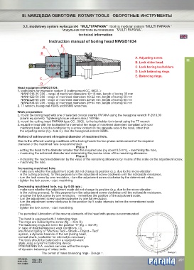
Instruction manual of boring head NWGD1034
E
A
B
A. Adjusting screw.
III.
B. Lock slider head.
C. Lock boring toolholders.
D. Lock balancing rings.
E. Balancing rings.
C
D
Head equipment NWGD1034:
1. toolholders for internal in system S (cutting insert CC..0602..):
NWN1016-35 C06 – range of machined diameters 10÷16 mm, length of boring 35 mm
NWN1622-50 C06 - range of machined diameters 16÷22 mm, length of boring 50 mm
NWN2228-60 C06 - range of machined diameters 22÷28 mm, length of boring 60 mm
NWN2834-60 C06 - range of machined diameters 28÷34 mm, length of boring 60 mm
2. T7 wrench, hexagonal 4SMS and 6SMS wrenches.
Work preparation:
1. mount the boring head with one of selected conical shanks PAFANA using the hexagonal wrench P-2916.00
(shank equipment). Tightening torque value is about 160 Nm
2. mount the cutting insert PAFANA type CC.. 0602.. to the toolholder for internal using the T7 wrench
3. equip the head with the toolholder for internal of the range of machined diameters compliant with your
machining task. Lock the toolholder by a screw located on the opposite side of the head, other than
the adjusting screw (fig.- item C). Use the hexagonal wrench 6SMS.
Method of achievement of required diameter of machined hole.
Due to the different working conditions of the boring heads the two-phase achievement of the required
diameter of the machined hole is recommended.
Phase 1
- setting the head to the diameter smaller than the required one (by about 0.5 mm), - machining the hole,
- measuring the achieved diameter and determining the precise value of the remaining allowance.
Phase 2
- increasing the machined diameter by the value of the remaining allowance by means of the scale on the adjustment screw,
- machining the hole.
Increasing machined hole:
- make sure whether the adjustment scale did not change its position (e.g. due to the micro-vibration
in the cutting process); for this purpose turn the adjustment screw clockwise until the noticeable resistance,
- turn the lock screw by one revolution, - turn the adjustment screw clockwise by the determined value,
- tighten the lock screw, - start machining.
Decreasing machined hole, e.g. by 0.05 mm :
- make sure whether the adjustment scale did not change its position (e.g. due to the micro-vibration
in the cutting process); for this purpose turn the adjustment screw clockwise until the noticeable resistance,
- unscrew the lock screw by one revolution, - remember the position of the adjustment scale,
- turn the adjustment screw counterclockwise by one full revolution,
- turn the adjustment screw clockwise to the position by 5 scale intervals before the remembered scale
position,
- tighten the lock screw, - start machining.
The periodical lubrication of the moving elements of the head with grease is recommended.
The head is equipped with 2 balancing rings.
The rings are locked by the screw (fig. – item D).
The balancing rings are set in the position “0” (fig. – item E).
In case of disadvantageous work conditions, i.e.
insufficient rigidity of “Machine Tool – Shank – Object – Tool”
system, a dynamic balance of the set (boring head,
The center of mass
conical shank, toolholder for internal) is necessary.
The tools should be balanced in a ready-for-work
state using a dynamic balancing device.
PFN PAFANA S.A. renders services within the scope
of dynamic balancing of rotary tools.
The center of mass balancing rings - Design 1. Design 1.
info.tech. 182-184 ® 207
tech.info. 206-213
тех.инфо.