
Page 212 - Pafana
P. 212
III. NARZĘDZIA OBROTOWE ROTARY TOOLS ОБОРОТНЫЕ ИНСТРУМЕНТЫ
3.1. modułowy system wytaczarski “MULTI PAFANA” / boring modular system “MULTI PAFANA “
модульная система вытачивания “MULTI PAFANA”.
technical information
Instruction manual for boring heads NWGD
diameter range 34 -260
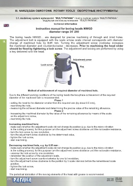
The boring heads NWGD… are designed for precise machining of through and blind holes.
The adjustment bolt is equipped with the scale whose scale interval corresponds with diameter
III.
change of machined hole by 0.01 mm. Turning the adjustment screw clockwise increases
the machined diameter and counterclockwise - decreases. Prior to machining the head slider
should be fixed by tightening a lock screw. The adjustment and locking are performed by using
a key delivered with the head.............................................................................................................
Adjustment screw
Lock screw
Key
Method of achievement of required diameter of machined hole.
Due to the different working conditions of the boring heads the two-phase achievement of the required
diameter of the machined hole is recommended.
Phase 1
- setting the head to the diameter smaller than the required one (by about 0.5 mm),
- machining the hole,
- measuring the achieved diameter and determining the precise value of the remaining allowance.
Phase 2
- increasing the machined diameter by the value of the remaining allowance by means of the scale
on the adjustment screw,
- machining the hole.
Increasing machined hole:
- make sure whether the adjustment scale did not change its position (e.g. due to the micro-vibration
in the cutting process); for this purpose turn the adjustment screw clockwise until the noticeable resistance,
- turn the lock screw by one revolution,
- turn the adjustment screw clockwise by the determined value,
- tighten the lock screw,
- start machining.
Decreasing machined hole, e.g. by 0.05 mm :
- make sure whether the adjustment scale did not change its position (e.g. due to the micro-vibration
in the cutting process); for this purpose turn the adjustment screw clockwise until the noticeable resistance,
- unscrew the lock screw by one revolution,
- remember the position of the adjustment scale,
- turn the adjustment screw counterclockwise by one full revolution,
- turn the adjustment screw clockwise to the position by 5 scale intervals before the remembered scale
position,
- tighten the lock screw,
- start machining.
The periodical lubrication of the moving elements of the head with grease is recommended.
® info.tech.
210 182-184 tech.info.
206-213
тех.инфо.