
Page 173 - Pafana
P. 173
III. NARZĘDZIA OBROTOWE ROTARY TOOLS ОБОРОТНЫЕ ИНСТРУМЕНТЫ
frezy składane milling cutters фрезы сборные
technical information
Slot milling cutters three - sided, adjustable : 676.24-125-1416
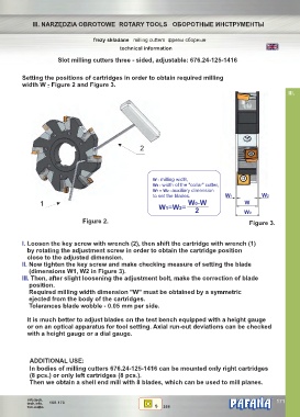
Setting the positions of cartridges in order to obtain required milling
width W - Figure 2 and Figure 3.
III.
2
W - milling width,
W0 - width of the "collar" cutter,
W1 = W2 - auxiliary dimension
to set the blades. W1 W2
1 W0-W W
W1=W2=
2 W0
Figure 2. Figure 3.
I. Loosen the key screw with wrench (2), then shift the cartridge with wrench (1)
by rotating the adjustment screw in order to obtain the cartridge position
close to the adjusted dimension.
II. Now tighten the key screw and make checking measure of setting the blade
(dimensions W1, W2 in Figure 3).
III. Then, after slight loosening the adjustment bolt, make the correction of blade
position.
Required milling width dimension "W" must be obtained by a symmetric
ejected from the body of the cartridges.
Tolerances blade wobble - 0.05 mm per side.
It is much better to adjust blades on the test bench equipped with a height gauge
or on an optical apparatus for tool setting. Axial run-out deviations can be checked
with a height gauge or a dial gauge.
ADDITIONAL USE:
In bodies of milling cutters 676.24-125-1416 can be mounted only right cartridges
(8 pcs.) or only left cartridges (8 pcs.).
Then we obtain a shell end mill with 8 blades, which can be used to mill planes.
info.tech. ® 171
tech.info. 168-173
тех.инфо. S 296